السلام عليكم و رحمه الله و بركاته
عندى سؤال عن الميجر الذى دائما مااجد ملفات عن كيفيه تشغيله و التعامل معه و لكنى لا افهم تكوينه الداخلى و عند و جدت داتا عن تكوينه تهت فااتمنى ان يساعدنى من لديه خبره ان شاء الله عن الموضوع فى الخطا الذى وقعت فيه
يوجد لدى 3 اطراف 2 ارضى لماذا و اتمنى لو يتم توضيح مسارات التيار
المولد الداخلى خرجه يصل الى الملف
B
و لكن الملف
A
من ان ياتى التيار الذى يمر فيه فيولد مجال مغناطيسى يتفاعل بطريقه ما حتى يظهر لى بالنهايه القراءه على الاوميتر
The megger is a portable instrument used to measure insulation resistance. The megger consists of a hand-driven DC generator and a direct reading ohm meter. A simplified circuit diagram of the instrument is shown in Figure 17.
The moving element of the ohm meter consists of two coils, A and B, which are rigidly mounted to a pivoted central shaft and are free to rotate over a C-shaped core (C on Figure 17). These coils are connected by means of flexible leads. The moving element may point in any meter position when the generator is not in operation.
As current provided by the hand-driven generator flows through Coil B, the coil will tend to set itself at right angles to the field of the permanent magnet. With the test terminals open, giving an infinite resistance, no current flows in Coil A. Thereby, Coil B will govern the motion of the rotating element, causing it to move to the extreme counter-clockwise position, which is marked as infinite resistance.
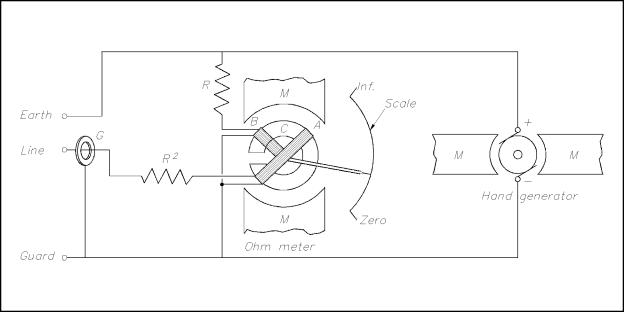
Figure 17 Simple Megger Circuit Diagram
Coil A is wound in a manner to produce a clockwise torque on the moving element. With the terminals marked "line" and "earth" shorted, giving a zero resistance, the current flow through the Coil A is sufficient to produce enough torque to overcome the torque of Coil B. The pointer then moves to the extreme clockwise position, which is marked as zero resistance. Resistance (Rl) will protect Coil A from excessive current flow in this condition.
When an unknown resistance is connected across the test terminals, line and earth, the opposing torques of Coils A and B balance each other so that the instrument pointer comes to rest at some point on the scale. The scale is calibrated such that the pointer directly indicates the value of resistance being measured.


