تفضل أخي الكريم
Simple combination lock
PARTS AND MATERIALS
4001 quad NOR gate (Radio Shack catalog # 276-2401)
4070 quad XOR gate (Radio Shack catalog # 900-6906)
Two, eight-position DIP switches (Radio Shack catalog # 275-1301)
Two light-emitting diodes (Radio Shack catalog # 276-026 or equivalent)
Four 1N914 "switching" diodes (Radio Shack catalog # 276-1122)
Ten 10 k

resistors
Two 470
resistors
Pushbutton switch, normally open (Radio Shack catalog # 275-1556)
Two 6 volt batteries
Caution! Both the 4001 and 4070 ICs are CMOS, and therefore sensitive to static electricity!
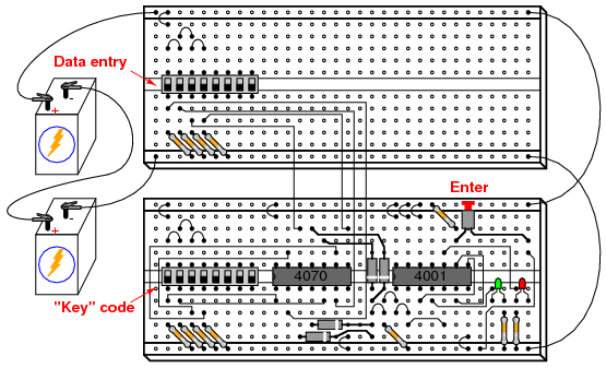
This experiment may be built using only one 8-position DIP switch, but the concept is easier to understand if two switch assemblies are used. The idea is, one switch acts to hold the correct code for unlocking the lock, while the other switch serves as a data entry point for the person trying to open the lock. In real life, of course, the switch assembly with the "key" code set on it must be hidden from the sight of the person opening the lock, which means it must be physically located elsewhere from where the data entry switch assembly is. This requires two switch assemblies. However, if you understand this concept clearly, you may build a working circuit with only one 8-position switch, using the left four switches for data entry and the right four switches to hold the "key" code.
For extra effect, choose different colors of LED: green for "Go" and red for "No go."
CROSS-REFERENCES
Lessons In Electric Circuits, Volume 4, chapter 3: "Logic Gates"
LEARNING OBJECTIVES
Using XOR gates as bit comparators
How to build simple gate functions with diodes and a pullup/down resistor
Using NOR gates as controlled inverters
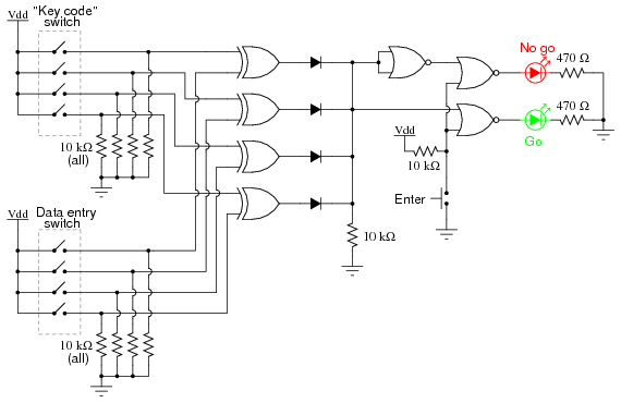
SCHEMATIC DIAGRAM
 ILLUSTRATION
 INSTRUCTIONS
This circuit illustrates the use of XOR (Exclusive-OR) gates as bit comparators. Four of these XOR gates compare the respective bits of two 4-bit binary numbers, each number "entered" into the circuit via a set of switches. If the two numbers match, bit for bit, the green "Go" LED will light up when the "Enter" pushbutton switch is pressed. If the two numbers do not exactly match, the red "No go" LED will light up when the "Enter" pushbutton is pressed.
Because four bits provides a mere sixteen possible combinations, this lock circuit is not very sophisticated. If it were used in a real application such as a home security system, the "No go" output would have to be connected to some kind of siren or other alarming device, so that the entry of an incorrect code would deter an unauthorized person from attempting another code entry. Otherwise, it would not take much time to try all combinations (0000 through 1111) until the correct one was found! In this experiment, I do not describe how to work this circuit into a real security system or lock mechanism, but only how to make it recognize a pre-entered code.
The "key" code that must be matched at the data entry switch array should be hidden from view, of course. If this were part of a real security system, the data entry switch assembly would be located
outside the door, and the key code switch assembly
behind the door with the rest of the circuitry. In this experiment, you will likely locate the two switch assemblies on two different breadboards, but it is entirely possible to build the circuit using just a single (8-position) DIP switch assembly. Again, the purpose of the experiment is not to make a real security system, but merely to introduce you to the principle of XOR gate code comparison.
It is the nature of an XOR gate to output a "high" (1) signal if the input signals are
not the same logic state. The four XOR gates' output terminals are connected through a diode network which functions as a four-input OR gate: if
any of the four XOR gates outputs a "high" signal -- indicating that the entered code and the key code are not identical -- then a "high" signal will be passed on to the NOR gate logic. If the two 4-bit codes are identical, then none of the XOR gate outputs will be "high," and the pull-down resistor connected to the common sides of the diodes will provide a "low" signal state to the NOR logic.
The NOR gate logic performs a simple task: prevent either of the LEDs from turning on if the "Enter" pushbutton is not pressed. Only when this pushbutton is pressed can either of the LEDs energize. If the Enter switch is pressed and the XOR outputs are all "low," the "Go" LED will light up, indicating that the correct code has been entered. If the Enter switch is pressed and any of the XOR outputs are "high," the "No go" LED will light up, indicating that an incorrect code has been entered. Again, if this were a real security system, it would be wise to have the "No go" output do something that deters an unauthorized person from discovering the correct code by trial-and-error. In other words, there should be some sort of
penalty for entering an incorrect code. Let your imagination guide your design of this detail!